konokaiden
could you put a link to the RJ12 headers you bought?
"Build It Yourself" Log
Sure. The first ones I bought were like this, and the asymmetry was a problem:
https://www.showmecables.com/rj12-dec-modular-connector-6p6c-flat-cable-10-pack?gclid=CjwKCAiAgJWABhArEiwAmNVTB5h94ehb-2P8uW48seKwgkdJOfu4iBi0mYHzCo4MPCOXXuNp7HxqrBoCLRAQAvD_BwE
Then I ordered these, and it still didn't fit...
https://www.grainger.com/product/13U661?gclid=CjwKCAiAgJWABhArEiwAmNVTB9k08wPWEnQFB_h5ldtvTJU7dccs5Rx8i6bj015b7KarD_MAggewKRoCKdQQAvD_BwE&cm_mmc=PPC:+Google+PLA&ef_id=CjwKCAiAgJWABhArEiwAmNVTB9k08wPWEnQFB_h5ldtvTJU7dccs5Rx8i6bj015b7KarD_MAggewKRoCKdQQAvD_BwE:G:s&s_kwcid=AL!2966!3!281698275252!!!g!470952775171!&gucid=N:N:PS:Paid:GGL:CSM-2295:4P7A1P:20501231
and because of the limited image, it should be identical to this:
https://www.googleadservices.com/pagead/aclk?sa=L&ai=DChcSEwjQl4bD2qXuAhUzOLMAHb4nBXIYABAJGgJ5bQ&ohost=www.google.com&cid=CAESQeD2GI91JYkA5xEOqgDFcujQf77I0E8-2VQNxznbCablXRb8xaingP4DdnoSh_n0bbMfjvzcPRf2JI4fZY8RT63G&sig=AOD64_2nRGmy_YdbZyVY4qIrLYErTis4Mg&ctype=5&q=&ved=2ahUKEwibuf3C2qXuAhVJwlkKHQGcAK0Q9aACegQIDRBL&adurl=
The first one looks exactly like the one I bought, the second one is the exact entry that I bought, and the third one looks like the second one, except you get more angles to look at it from.
konokaiden Then I ordered these, and it still didn't fit...
They look like the correct one, but that supplier is not providing a datasheet were to check the measurements.
Have you tried crimping them before trying to fit them in the connector? before crimping the contacts stick out of the plastic body, perhaps that's the problem.
Otherwise try getting the connectors from the same supplier you've got the jack. they put a link to the datasheet on each product page, double check the measurements there
I wondered about the contacts being the problem, so I'll crimp those that I have first and see if that works out. Otherwise, I'll look into getting some headers from Wurth.
Okay, once crimped, the wiring fits perfectly.
So here's where I am now:
Built the circuits: Check (need to fix a couple that had soldering issues)
Set up the notochord for SSH: Check
Wire a few Kceptors to the Hub: Check
Set up Blender app: Check
Next steps:
1) Print box for Kceptors and Hub (and Pi) to sit in.
2) Fix the 5 Kceptors that lost resistors due to bad soldering
3) Get Velcro to attach everything to body
4) Get battery pack for Pi
5) Spray the 3D printed boxes with Anti-static spray to reduce risk of electrical damage (already own spray)
6) Calibrate the Kceptors (?)
7) Use the system
My only question on Number 6, do each of them have to be calibrated with the cardboard box before using the system, and if so, how often is one calibration supposed to be good for?
great!
I would suggest you to connect all the sensors and have the default_biped configuration working before doing the extra stuff like printing the boxes, attaching with velcro, etc. That way if you need to fix something in the hardware you won't need to undo those parts of the process.
The sensors should be calibrated only once, and they should last that way for a long time. Sometimes when mounting them on a box or support the physical properties of the sensor change and they should be calibrated again.
Keep in mind that the cardboard calibration box is just a helper to better guide you in the process of calibrating. You can eventually do the same procedure without it
Yeah, my actual order to things is to get the 5 sensors which lost a resistor fixed, then wire it all, then 3D print the boxes (which open and close, so I can remove a kceptor if needed without any trouble). Then I'd do the velcro, because again, I'm just feeding it around a box, so it's easy to undo, and then I'd deal with Blender.
How would I get the default_biped_configuration working without having it on my actual body or without calibrating it all first?
- Edited
konokaiden How would I get the default_biped_configuration working without having it on my actual body or without calibrating it all first?
You can just lay them all on a table, connect them together with the Hub and raspberry and run the notochord
with the default_biped
configuration.
I've seen many users having problems at this step: perhaps connectivity issues, soldering problems, software misconfiguration, etc.
If you spot these problems at this step they are easier to solve, and saves you the frustration of doing a lot of work to find out that a tiny detail forces you to undo some of it.*
Once you have it working you can also go ahead and send the data to blender. You will get a mess of entangled bones, probably slowly drifting because of the lack of calibration, but you should be able to see a particular bone moving if you move one of the physical sensors. If I were you I would check each sensor is responding using that method at this stage.
At this point you will be pretty certain that the core of your system is indeed working, and it would be a good time to wrap up the details like fixings or so..
(*)
This is a general rule I (and many others) apply to complex developments, it's know as the "Fail fast rule": It's better to identify all the possible errors of your system at the beginning, before start doing the finishes
PS: If you do the table test, please post some photos or videos of it, we can use them to explain the process to others easily
I have the wires crimped and such now. I'll post pics of that later. I hope to do the table test later today, and I'll probably post a video of that, since I'll be moving between two rooms.
Hi. Ä°s there anyone who already complete this mocap himself? Ä°s there a person to do so, can he tell how much time and money did he spend in total?
- Edited
daylanKifky Mine is probably the worst example since I had all passive components in stock.
I had to buy the i2c address translator ICs and the IMU ICs. The boards cost me around 20$ plus 20-25$ in shipping.
Assembly took a relaxed weekend.
regards,
Val
So, I'm having issues with the table test...
I've tried reversing how they are plugged into the hub, thinking they might've been backwards, but the results were identical... All 15 Kceptors are plugged in, the power configuration goes from power bank to hub to rasp pi. And I have all the cables done correctly. The only visual issue I have is that none of the hub or kceptor indicator lights are on, but since the rasp pi indicator lights are working,power seems to be moving from the power supply to the rasp pi through the hub properly.
try to run
notochord --scan
first. It will tell you how many KCs it's finding and in which port
Then, in order to use the 15 sensors of the default_biped
configuration you should run the notochord with the -c
flag
notochord -c default_biped.xml
Well despite the fact that the hub is sending power to the pi, it's saying it can't find the hub:
try running
i2cdetect -y 1
and paste the output here
Hmm, that doesn't look good...
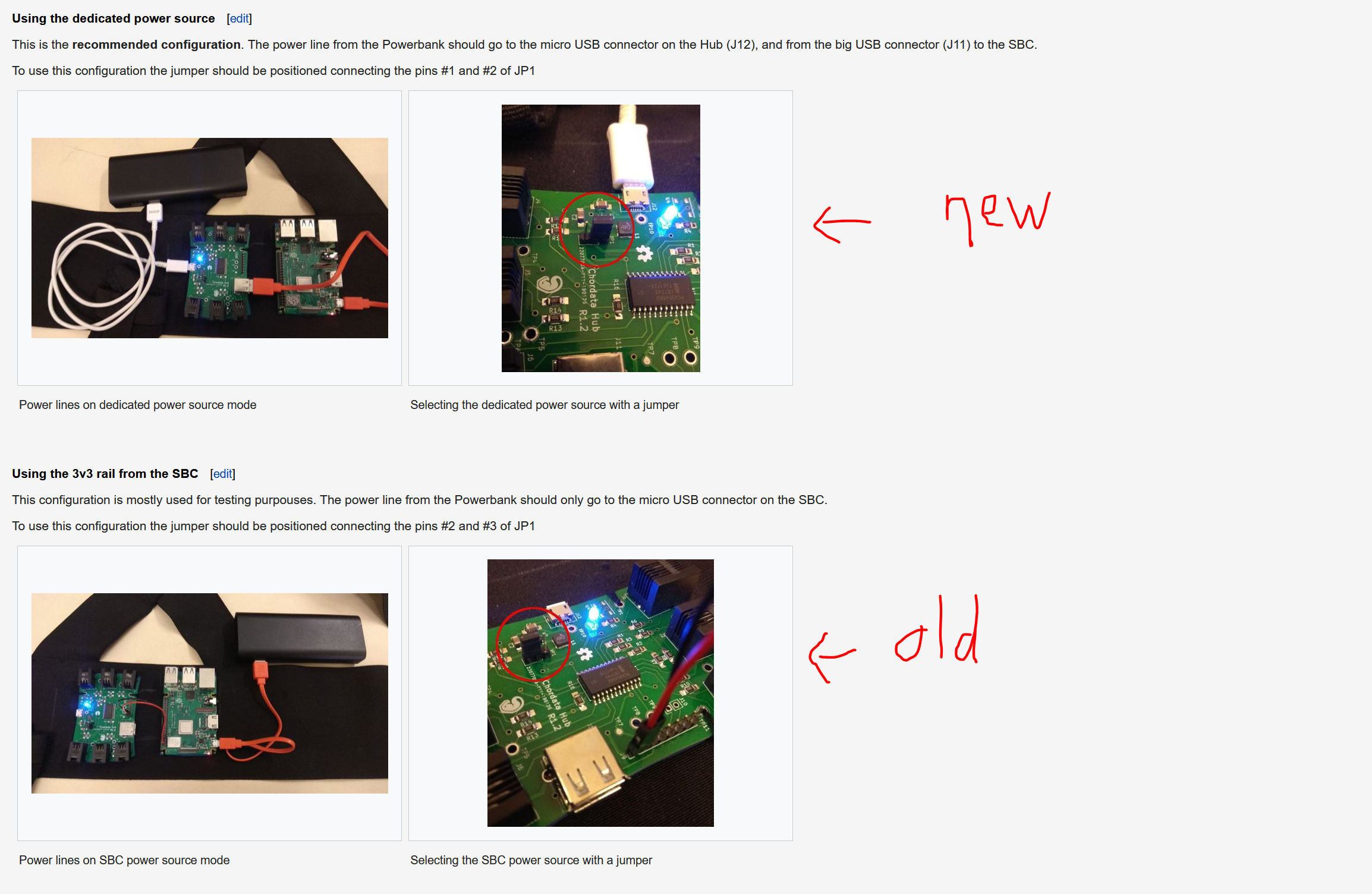
I should also mention, in case I haven't before, that the indicator light on the Hub isn't on. This is true of the KCeptors, but with the hub, I have seen it flicker on. At the time, I was fiddling with the old vs new power settings. The "old" setting being the one where you connect the power to the Pi, and then use jumpers from 6 or so of those pins to the first 6 pins on the Hub. It didn't consistently stay on that way either, but it did light up for a bit, and then I bumped it and the light went back off.
Normally I'd consider that a problem with powering things, except the "new" power configuration uses the USBs instead of those pins, plus the jumper on the three pin is in the other position. Plus the Pi is getting power, it's just the indicator light that isn't lighting up. So I'm not sure what to make of it, whether power is getting to certain sections of the board and not others, or whether I'm getting a little power everywhere, but not necessarily a lot of power. Now I assume the test you gave me to do is a test of whether my chip is working or not. But I just want to mention that it could be a power problem.
But yeah, I wanted to mention that the hub light has been on before, but isn't on normally, and I have tried both power settings, with slightly different results related by coincidence, not configuration. So I don't actually know where the power problem would be, assuming it is a power problem.
- Edited
In fact your raspberry is not able to detect the HUB, you should see a positive 73
value if it does.
Are you testing it with the KCeptors connected? If so you can try to test it once with no KCeptor connected in order to verify if you are having a problem like this one.
If the led flickers it's probably due so an loose connection at some place in the HUB. A good idea would be to inspect the soldered pins and pads under a microscope or magnifying glass.
Or the buck converter might be damaged, but this only applies to the "new" power configuration.
In any case you can try the procedure I suggested here to troubleshoot the power source with a tester